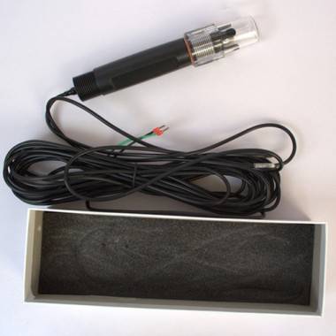
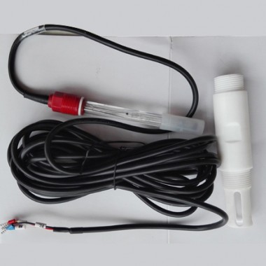
Chapter 1 Specification
| Specification | Details |
| Power Supply | 12VDC |
| Size | Diameter 30mm*Length195mm |
| Weight | 0.2KG |
| Main Material | Black polypropylene cover, Ag/Agcl reference gel |
| Waterproof Grade | IP68/NEMA6P |
| Measuring Range | 0-14pH |
| Measurement Accuracy | ±0.1pH |
| Pressure Range | ≤0.6Mpa |
| Alkali Error | 0.2pH(1mol/L Na+ pH14)(25℃) |
| Measuring Temperature Range | 0 ~ 80 ℃ |
| Zero Potential pH Value | 7±0.25pH(15mV) |
| Slope | ≥95% |
| Internal Resistance | ≤250MΩ |
| Response Time | Less than 10 seconds ( reaching to endpoint 95%) (After stirring) |
| Length of Cable | Standard cable length is 6 meters, which is extendable. |
Sheet 1 Specification of PH Sensor
| Specification | Details |
| Power Supply | 12VDC |
| Output | MODBUS RS485 |
| Protection Grade | IP65, it can achieve IP66 after potting. |
| Operating Temperature | 0℃ - +60℃ |
| Storage Temperature | -5℃ - +60℃ |
| Humidity | No condensation in the range of 5%~90% |
| Size | 95*47*30mm(Length*Width*Height) |
Sheet 2 Specification of Analog-to-Digital Conversion Module
There is no prior notice if any specification of the product changes.
Chapter 2 Product Overview
2.1 Product Information
pH describes the Potential of Hydrogen of the water body and its basic properties. If pH is less than 7.0, it means the water is acidic; If pH equals to 7.0, it means the water is neutral, and if pH is more than 7.0, it means the water is alkaline.
The pH sensor uses a composite electrode that combines the glass indicating electrode and the reference electrode to measure the pH of the water. The data is stable, performance is reliable, and installation is simple.
It is widely used in such fields as sewage plants, water works, water supply stations, surface water, and industries; Figure 1 provides the dimensional drawing which shows the size of the sensor.
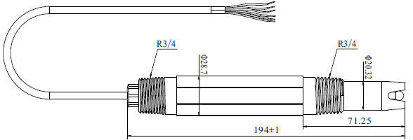
Figure 1 The size of the sensor
2.2 Safety Information
Please read this manual completely before opening the package, installing or using. Otherwise it may cause personal injury to the operator, or cause damage to equipment.
Warning labels
Please read all labels and signs on the instrument, and comply with the security label instructions, otherwise it may cause personal injury or equipment damage.
When this symbol appears in the instrument, please refer to the operation or safety information in the reference manual.
While this symbol indicates an electric shock or risk of death from electric shock.
Please read this manual completely. Pay particular attention to some notes or warnings, etc. To ensure that the protective measures provided by the equipment are not destroyed.
Chapter 3 Installation
3.1 Installation of Sensors
The specific installation steps are as follows:
a. Install the 8 (mounting plate) on the railing by the pool with 1 (M8 U-shape clamp) at the sensor mounting position;
b. Connect 9 (adapter) to 2 (DN32) PVC pipe by glue, pass the sensor cable through Pcv pipe until the sensor screws into 9 (adapter), and do waterproof treatment;
c. Fix 2 (DN32 tube) onto 8 (mounting plate) by 4 (DN42U-shape clamp).
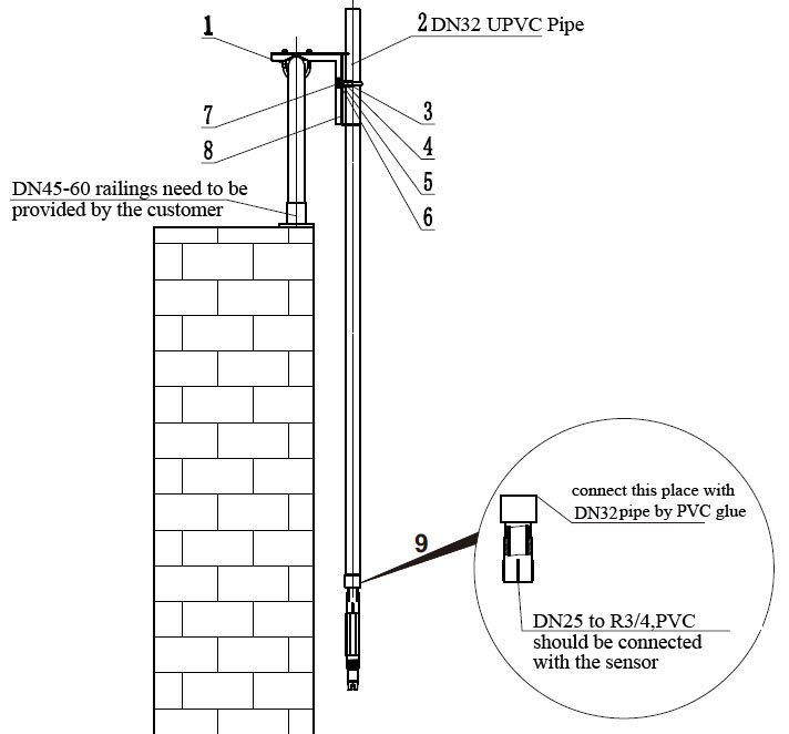
Figure 2 Schematic Diagram on the Installation of Sensor
| 1-M8U-shape Clamp(DN60) | 2- DN32 Pipe (outside diameter 40mm) |
| 3- Hexagon Socket Screw M6*120 | 4-DN42U-shape Pipe Clip |
| 5- M8 Gasket(8*16*1) | 6- M8 Gasket(8*24*2) |
| 7- M8 Spring Shim | 8- Mounting Plate |
| 9-Adaptor(Thread to Straight-through) | |
3.2 Sensor Linking
(1)Firstly, Connect the sensor connector to the analog-to-digital converter module as shown below.
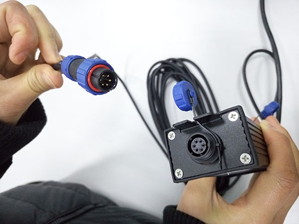
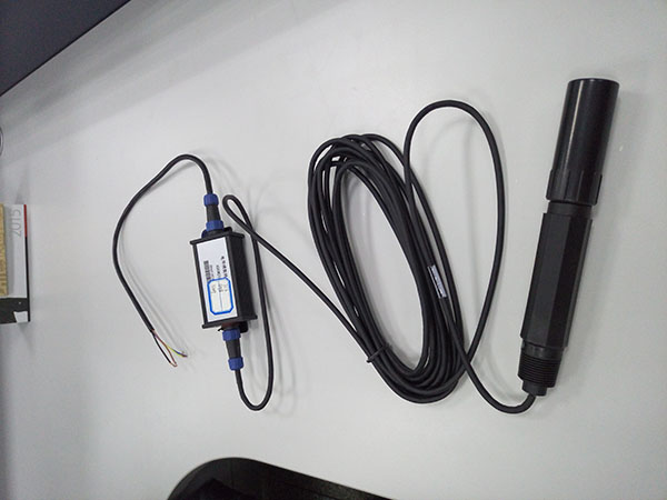
(2)And then respectively connect the core of cable behind the module in accordance with the definition of the core.The correct connection between the sensor and the definition of the core:
| Serial Number | 1 | 2 | 3 | 4 |
| Sensor Wire | Brown | Black | Blue | Yellow |
| Signal | +12VDC | AGND | RS485 A | RS485 B |
(3)PH analog-to-digital converter module joint has a shorter heat shrinkable tube can be used for grounding.When using the heat shrinkable tube must be cut open, revealing a red line to ground.

Chapter 4 Interface and Operation
4.1 User Interface
① The sensor uses RS485 to USB for connecting to the computer, and then install the CD-ROM software Modbus Poll to the upper computer, double-click and execute the Mbpoll.exe to follow the prompts for installation, eventually, you can enter the user interface.
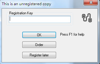
② If it’s the first time, you need to register first. Click "Connection" on the menu bar and select the first line in the drop-down menu. Connection Setup will display the dialog box for registration. As the figure shown below. Copy the attached registration code to the Registration Key and click "OK" to complete the registration.
4.2 Parameter Setting
1. Click Setup on the menu bar, select Read / Write Definition, and then click OK after following the Figure below to set the preferences.
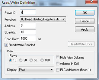
Note: The initial default of the slave address (Slave ID) is 2, and when the slave address is changed, the slave address is communicated with the new address and the next slave address is also the most recently changed address.
2. Click Connection on the menu bar, select the first line in the drop-down menu Connection setup, set it as the Figure shown below, and click OK.
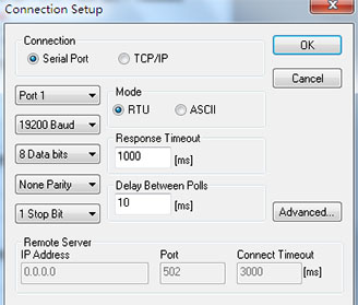
Note: Port is set according to the port number of the connection.
Note: If the sensor has been connected as described, and the software Display status appears No Connection, it means it is not connected. Remove and replace the USB port or check the USB to RS485 converter, repeat the above operation until the sensor connection is successful.
Chapter 5 Calibration of Sensor
5.1 Preparation for Calibration
Before the test and calibration, some preparation need to be done for the sensor, which are as follows:
1) Before test, remove the test soak bottle or rubber cover which are used to protect the electrode from the soak solution, immerse the measuring terminal of the electrode into distilled water, stir and make it clean; then pull the electrode out of the solution, and clean the distilled water with filter paper.
2) Observe the inside of the sensitive bulb to see if it is full of liquid, if bubbles have been found, the measuring terminal of the electrode should be shaken gently downwards (like shaking body thermometer) to remove the bubbles inside the sensitive bulb, otherwise it will affect the accuracy of the test.
5.2 PH Calibration
The pH sensor needs to be calibrated before use. Self-calibration can be done as following procedures. pH calibration requires 6.86 pH and 4.01 pH standard buffer solution, the specific steps are as follows:
1. Connect the sensor to the PC to ensure that the connection is correct and then put it into a buffer solution with a pH of 6.86 and stir in the solution at an appropriate rate.
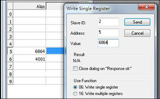
2. After the data stabilizes, double-click the data frame on the right side of 6864 and enter the buffer solution value of 6864 (representing a solution with a pH of 6.864) in the calibration neutral solution register, as shown in the following Figure, and then click Send.
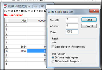
3. Remove the probe, rinse the probe with deionized water, and clean the residual water with filter paper; then place it in a buffer solution with a pH of 4.01 and stir in the solution at an appropriate rate. Wait until the data is stabilized, double-click the data box on the right side of the 4001 and fill the 4001 buffer solution (representing a pH of 4.001) in the calibration acid solution register, as shown in the following Figure, and then click Send.
4.After the acid point solution calibration is completed, the sensor will be washed with distilled water, and dried; then the sensor can be tested with the test solution, record the pH value after it’s stabilized.
Chapter 6 Communication Protocol
A.Analog-to-digital conversion module with MODBUS RS485 communication function, adopts RTU as its communication mode, with baud rate reaching to 19200, specific MODBUS-RTU table is as follows.
| MODBUS-RTU | |
| Baud Rate | 19200 |
| Data Bits | 8 bit |
| Parity Check | no |
| Stop Bit | 1bit |
B. It adopts MODBUS standard protocol, and the details of which are shown in the table below.
| PH Reading Data | |||
| Address | Data Type | Data Format | Memo |
| 0 | Float | 2 digits behind the decimal point are valid | PH Value(0.01-14) |
| 2 | Float | 1 digit behind the decimal point is valid | Temperature Value(0-99.9) |
| 9 | Float | 2 digits behind the decimal point are valid | Deviation Value |
| Calibration of PH preferences | |||
| 5 | Int | 6864(solution with a pH of 6.864) | Calibration Neutral Solution |
| 6 | Int | 4001(solution with a pH of 4.001)) | Calibration Acid Solution |
| 9 | Float9 | -14 to +14 | Deviation Value |
| 9997 | Int | 1-254 | Module Address |
Chapter 7 Care and Maintenance
In order to obtain the best measurement results, the regular care and maintenance are very needed. Care and maintenance mainly include the preservation of the sensor, checking the sensor to see if it is damaged or not and so forth. Meanwhile, the status of the sensor can be observed during care and inspection.
7.1 Sensor Cleaning
After long-term use, the slope and response speed of the electrode maybe slow down. The measuring terminal of the electrode can be immersed in 4% HF for 3~5 seconds or diluted HCl solution for 1~2 minutes. And then be washed with distilled water in potassium chloride (4M) solution and soaked for 24 hours or more to make it new.
7.2 Preservation of Sensor
During the interstitial period of the use of electrode, please try to clean the measuring terminal of the electrode with distilled water. If the electrode shall not be used for a long period of time; it should be rinsed and dried, and should be stored in the attached soak bottle or rubber cover containing the soaking solution.
7.3 Inspection on the damage of sensor
Check the appearance of the sensor and glass bulbs to see if they are damaged or not, if damages are found, it is necessary to replace the sensor in time. In the tested solution, if it contains sensitive bulb or junction-blocking substances leaving the electrode passivation, the phenomenon is significantly slower response time, slope reduction or unstable readings. As a result, it should be based on the nature of these contaminants, use the appropriate solvent for cleaning, thus making it new. Contaminants and appropriate Detergents are listed below for reference.
| Contaminants | Detergents |
| Inorganic Metallic Oxide | 0.1 mol/L HCl |
| Organic Grease Substance | Weak Alkalinity or Detergent |
| Resin, High Molecular Hydrocarbons | Alcohol, Acetone and Ethanol |
| Protein Blood Deposit | Acidity Enzyme Solution |
| Dyestuff Substance | Diluted Hypochlorous Acid Liquid |
Chapter 8 After-sales Service
If you have any questions or need repair service, please contact us as followings.
JiShen Water treatment Co., Ltd.
Add:No.2903, Building 9, C Area, Yuebei Park, Fengshou Road, Shijiazhuang, China .
Tel:0086-(0)311-8994 7497 Fax:(0)311-8886 2036
E-mail: info@watequipment.com
Website: www.watequipment.com
